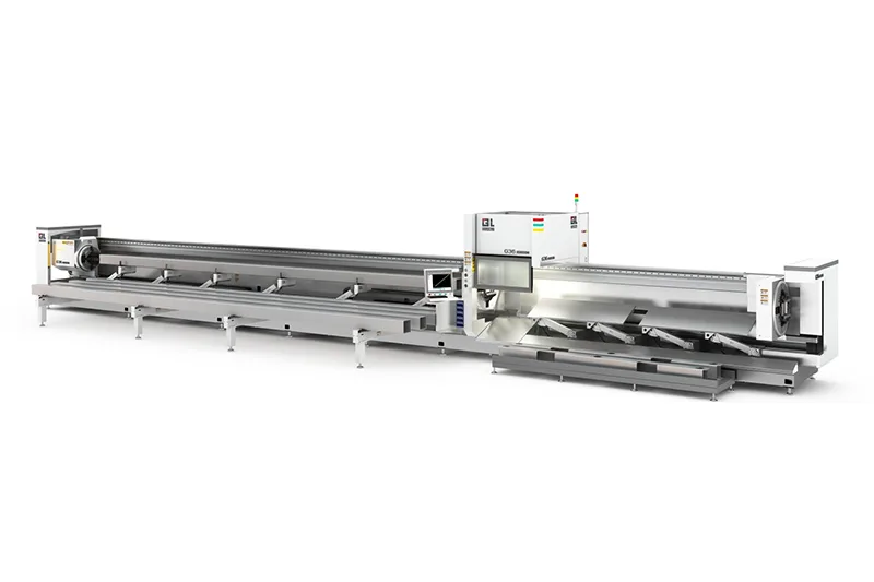
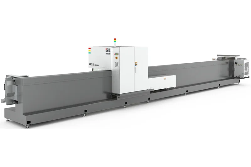

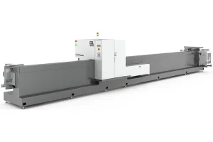
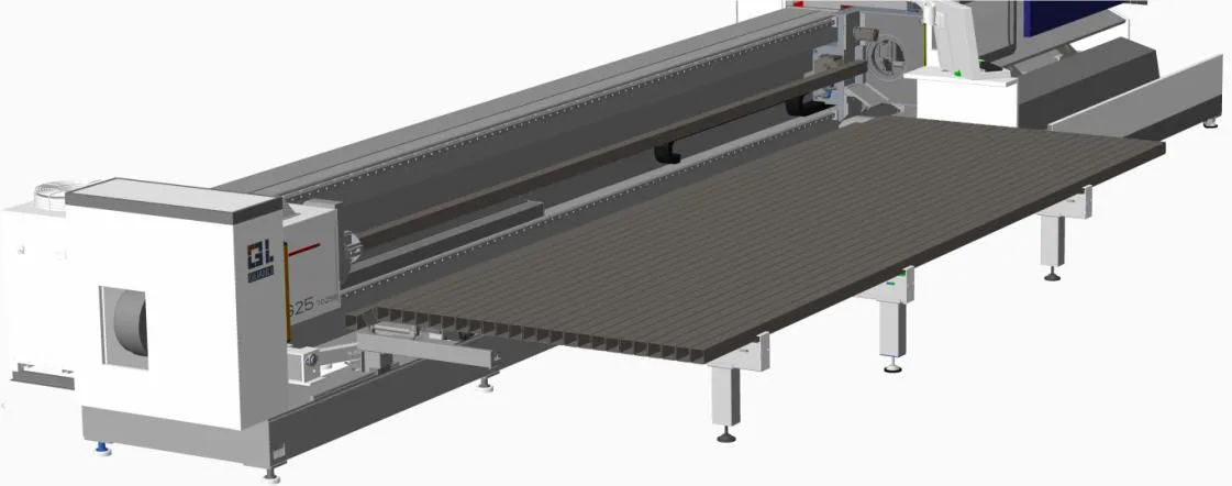
Top Quality Three Chuck Laser Tube Cutting Machine-9028C
The Top Quality Three Chuck Laser Tube Cutting Machine combines superior engineering with three-chuck technology to ensure exceptional precision and stability. Its high-performance cutting capabilities make it ideal for handling diverse tube materials, delivering consistent, top-tier results while minimizing waste and maximizing productivity.
Advantages and Characteristics
- High speed:The chuck has a high speed of 110RPM, acceleration of 1.1G, high cutting efficiency, standard configuration, and competitive advantages in overall price.
- Material saving:Chuck avoidance, 0-50mm ultra short tail material, breaking industry records and increasing material utilization.
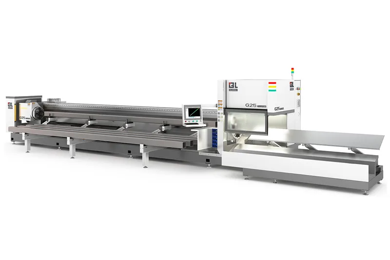
- High range compatibility:With a diameter of Ф15~275mm, it is compatible with circular pipes, square pipes, elliptical pipes, special-shaped pipes, etc., and has obvious advantages over thin-walled pipes.
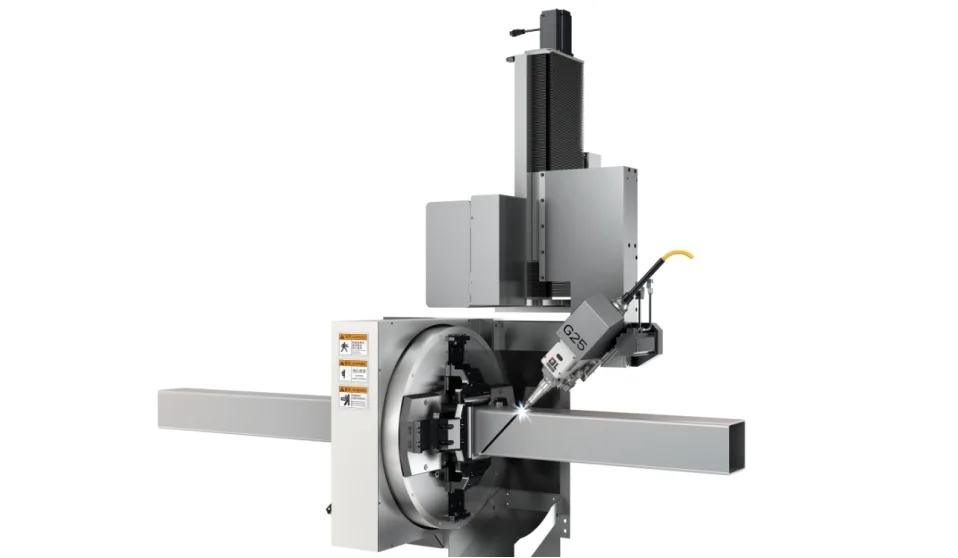
- High precision chuck:Real time stable control of clamping force, making machining accuracy more stable, automatic lubrication inside the chuck, reducing maintenance, and ensuring more stable operation of the structure.
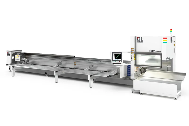
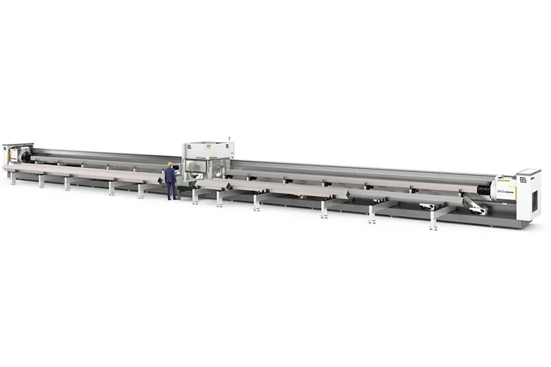
- Automatic feeding: Side suspended machine tool structure, standard semi-automatic feeding machine, high feeding cycle time of 20-3
- Stability: Combined with pneumatic support to prevent pipe swinging and achieve high stability in cutting.
- Low cost: There are no high cost consumables, and the main losses are electricity bills, protective lenses, and copper nozzles.
Video
Technical parameters of the whole machine
|
Category |
Attribute |
Parameter |
|
Device Attributes
|
outline dimension(mm) |
15500*2500*2800 |
|
Total weight (ton) |
10.5 |
|
|
Full power consumption of the whole machine(KW) |
45~50 |
|
|
Operating temperature(℃) |
0-40 |
|
|
machine range |
Processing schedule(mm) |
Round tube: ¢ 15- ¢ 275 |
|
Travel Range
|
One time clamping stroke of chuck(mm) |
¢ 15 to ¢ 150, and the second paragraph is from ¢ 150 to ¢ 275 |
|
Y/X/Z/U axis travel (mm) |
9500/250/450/Infinite rotation |
|
|
Repeated positioning
|
X/Y axis positioning accuracy (mm) |
±0.031000 |
|
X/Y axis repeat positioning accuracy (mm) |
±0.03 |
|
|
Rotation U-axis repeat positioning accuracy (arc minutes) |
≤5 |
|
|
Maximum rotational speed of U-axis (RPM) |
105 |
|
|
Speed and Acceleration
|
Maximum acceleration on X/Y axis |
1.1G |
|
Maximum idle running speed of X-axis (m/min) |
120 |
|
|
Maximum idle running speed of Y-axis (m/min) |
120 |
Key components and motion control
Machine bed
Made of welded plates and pipes, annealed at high temperature of 600 degrees Celsius for 4.5 hours, slowly cooled to 200-300 degrees Celsius in the furnace, and then air-cooled to eliminate internal bed stress. After rough machining, precision machining is carried out, greatly improving the rigidity and stability of the machine tool and ensuring its long-term stability and accuracy. The side mounted machine tool structure, paired with an automatic feeding machine, can effectively improve feeding efficiency and ease of unloading.
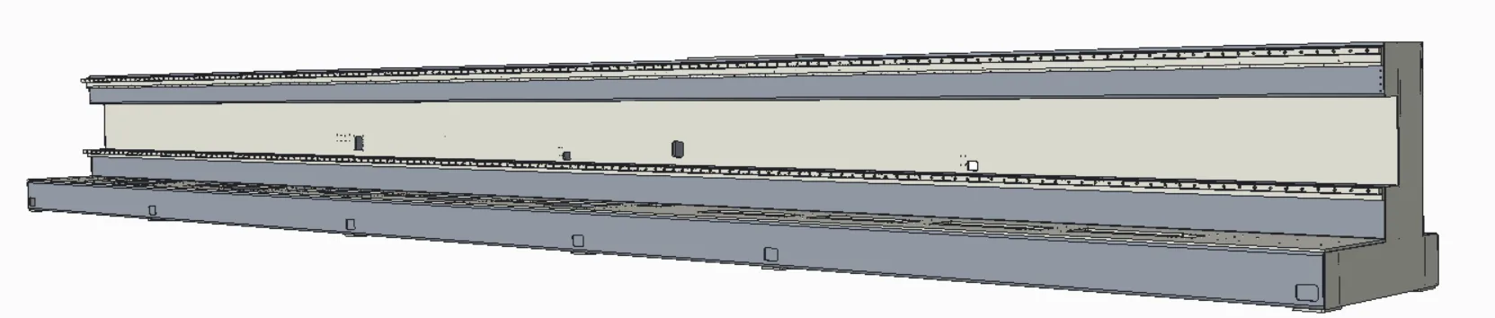
Rigidity: Welding of plates and pipes, the bed structure is connected horizontally and vertically by multiple reinforced rib tube plates to ensure rigidity.
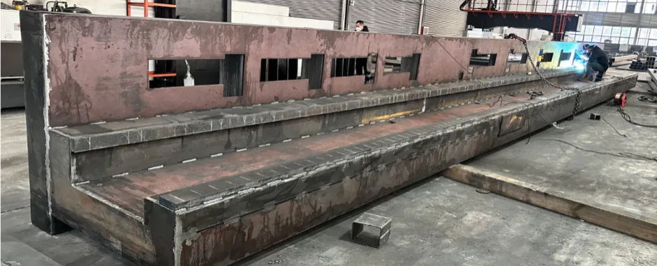
Welding: The welds on both sides are evenly distributed, symmetrically and staggered, reducing welding deformation.

Annealing report: Each bed frame number has an annealing report
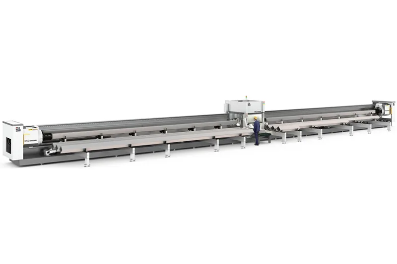
Fully automatic feeding machine, semi-automatic unloading machine
It can achieve automatic feeding of a bundle of raw materials, matching the feeding and positioning of the clamping jaws for feeding, and accurately clamping the profiles with the rear card to insert them forward.
The standard machine can store a maximum of one bundle of materials

Pneumatic flap lifting for pipe processing, reducing pipe swinging and avoiding accuracy deviation caused by pipe swinging.
Beam and X-axis/Z-axis devices
1. The crossbeam undergoes annealing to eliminate internal stress, ensuring the rigidity and stability of the moving components of the laser head. During the movement, the limit switch controls the stroke to limit, and there are also elastic buffer pads at both ends for mechanical limit, ensuring the safety of the system operation.
2. The Z-axis device is mainly used to achieve the up and down movement of the laser head. The up and down movement of the laser head is controlled by a CNC system servo motor, which drives the linear module and drives the Z-axis slider to reciprocate up and down. Both ends are controlled by proximity switches to ensure safe and reliable movement.