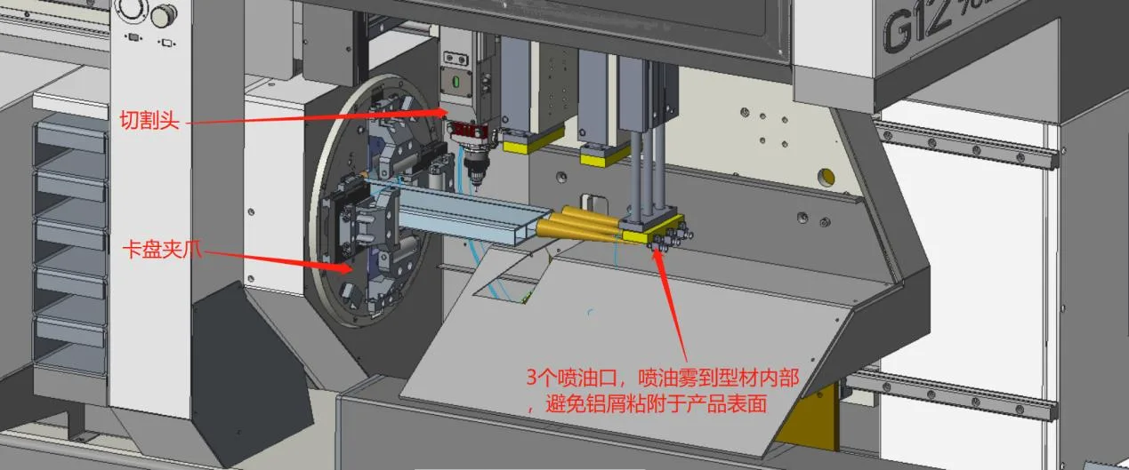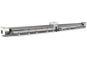
The High Precision Two Chuck Laser Tube Cutting Machine offers exceptional accuracy, securely holding tubes with dual chucks for superior performance on complex shapes and high-precision cuts across various materials.
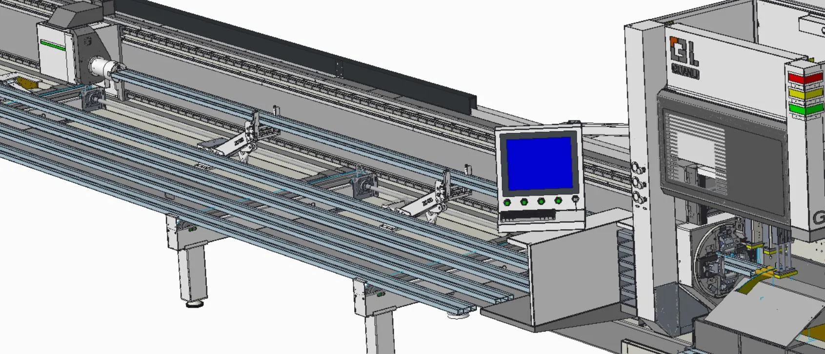
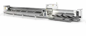
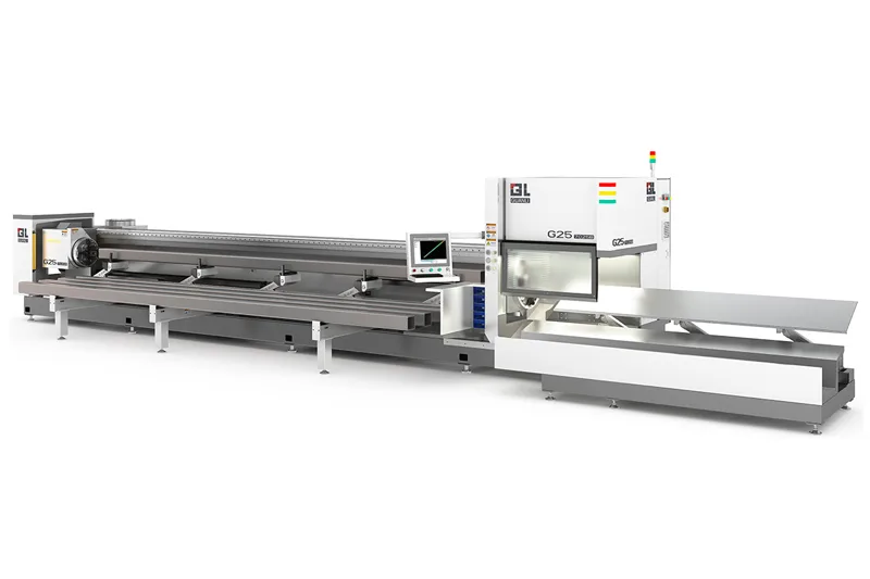
The CNC Fiber Two Chuck Laser Tube Cutting Machine combines advanced CNC technology and fiber laser cutting for precise, efficient tube processing. Its dual chuck system ensures stable support, delivering fast, high-quality cuts across various materials, ideal for automated production lines.
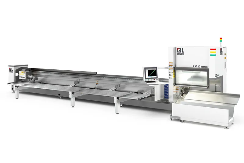
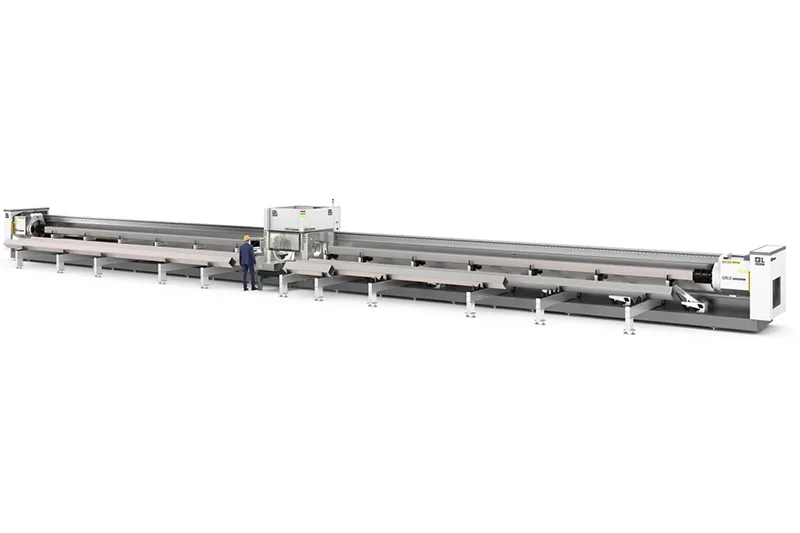
The High Speed Two Chuck Laser Tube Cutting Machine offers fast, precise cutting. Its dual chuck system ensures stable tube positioning, enabling accurate cuts across various materials and sizes, perfect for high-volume production.
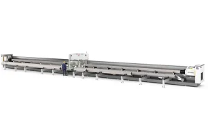
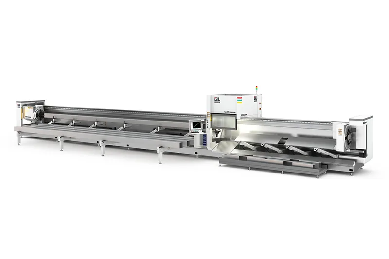
The High Control Force Four Chuck Laser Tube Cutting Machine uses a four-chuck system for enhanced clamping, ensuring stability and precision. Ideal for complex tube cutting, it offers maximum control and accuracy for large, heavy, or irregular tubes.